
Table des matières
Radar (RADAR, an acronym for Radio Detection And Ranging) is an active sensing technology that determines the distance, velocity, direction, and other attributes of a target by transmitting electromagnetic energy and analyzing the energy reflected back from objects in the environment.
In simple terms, radar works much like standing in a dark room and throwing rubber balls in all directions. Some balls hit objects and bounce back. If you know the speed and direction of the balls and measure the time they take to return, you can calculate the object’s position. Radar uses electromagnetic waves instead of rubber balls, but the principle is the same – measuring reflected signals to infer the target’s position relative to the radar.
1. The Core Working Principle of Radar
A système radar operates in a complete “transmit-reflect-receive-calculate” loop:
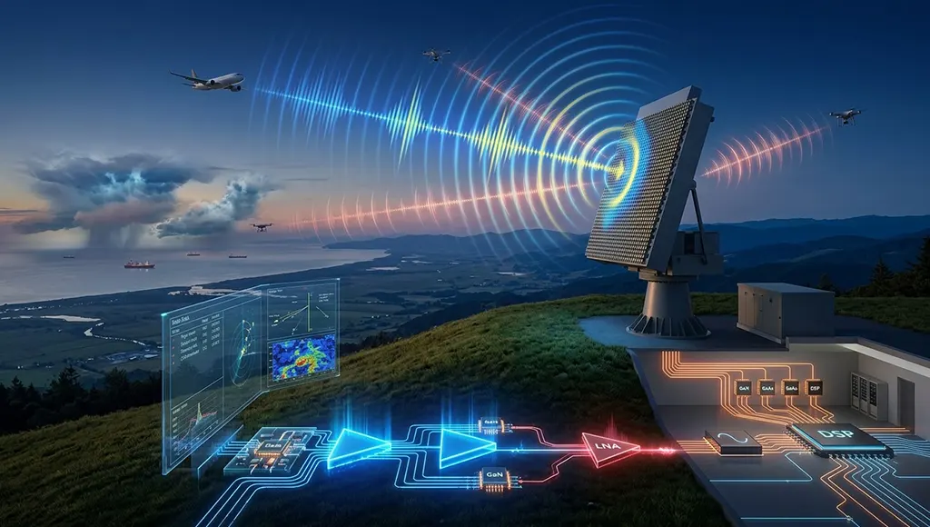
Step 1: Transmit – The radar’s transmitter generates high-frequency electromagnetic energy, typically in the microwave or millimeter-wave bands, and radiates it through the antenna in very short, high-intensity pulses or as a continuous wave.
Step 2: Reflect – The electromagnetic waves travel outward at the speed of light. When they encounter an object (aircraft, drone, weather system, terrain, etc.), a portion of the energy is scattered or reflected back toward the radar.
Step 3: Receive – The antenna captures the weak returning echoes, and the receiver amplifies and processes these extremely faint signals.
Step 4: Calculate – The system uses differences between the transmitted and received signals to compute the target’s range, velocity, and angle.
In a typical pulsed Doppler radar, the transmitter is active for only a tiny fraction of time. For example, the U.S. WSR-88D weather radar transmits pulses of just 1.57 microseconds, repeated about 1300 times per second. Over an hour of operation, the radar actually transmits for just over 7 seconds – the remaining 59 minutes and 53 seconds are spent “listening” for echoes.
2. The Three Fundamental Measurements of Radar
2.1 Range: The Time‑of‑Flight Method
Radar measures range by calculating the round‑trip time between transmitting a pulse and receiving its echo. Electromagnetic waves travel at approximately 300,000 kilometers per second in a vacuum. The formula for target range is:
Range = (Speed of Light × Round‑Trip Time) / 2
The division by two accounts for the fact that the signal travels from the radar to the target and back – the round‑trip distance is twice the one‑way range.
2.2 Velocity: The Doppler Effect
Radar measures target velocity through the Doppler Effect. When a radar pulse strikes a moving target, the frequency of the returned wave is shifted – compressed if the target is approaching the radar, stretched if it is moving away.
This phenomenon is analogous to the acoustic Doppler effect – the pitch of a police siren rises as it approaches you and falls as it moves away. Radar measures the Décalage de fréquence Doppler between the transmitted and received signals to calculate the target’s radial velocity (its speed directly toward or away from the radar). Modern weather radars and air‑surveillance radars are almost all Doppler radars for this reason.
2.3 Angle: Direction Finding
Radar determines the target’s angular position by the direction in which the antenna is pointing when the echo is received. In mechanically scanned radars, the antenna rotates and records the azimuth angle at the moment of the return. In phased‑array radars, the beam is steered electronically, and the system always knows the beam’s pointing angle.
3. Main Components of a Radar System
A complete radar system consists of the following core components:
| Composant | Fonction |
|---|---|
| Frequency Synthesizer | Generates the radar signal |
| Émetteur | Amplifies the signal to high power and radiates it |
| Antenne | Directs the electromagnetic energy into space and collects returning echoes |
| Récepteur | Amplifies and processes the extremely weak echo signals, extracting them from noise |
| Processeur de signaux | Performs mathematical operations – matched filtering, pulse compression, Doppler processing – to extract target information |
| Display/Data Output | Présente les données traitées aux opérateurs ou les transmet à des systèmes automatisés |
4. Major Types of Radar
4.1 By Architecture
Radar monostatique – Uses a single antenna for both transmission and reception, with a transmit‑receive switch to protect the receiver during the high‑power transmit interval. This is the most common architecture.
Radar bistatique – The transmitter and receiver are separated by a significant distance.
Phased‑Array Radar – Replaces a mechanically rotating dish with an array of electronically steered antenna elements. By adjusting the phase of each element, the beam can be pointed in any direction within microseconds.
4.2 By Operating Mode
Radar à impulsions – Transmits very short, high‑intensity pulses and listens for echoes between pulses. Most surveillance and tracking radars use pulsed waveforms.
Continuous‑Wave (CW) Radar – Transmits continuously, requiring physically separate transmit and receive antennas to prevent leakage.
Frequency‑Modulated Continuous‑Wave (FMCW) Radar – Adds frequency modulation to continuous transmission, enabling both range and velocity measurements.
5. Radar Frequency Bands and Applications
Different frequency bands offer different trade‑offs between resolution, detection range, and atmospheric penetration:
| Groupe | Gamme de fréquences | Applications typiques |
|---|---|---|
| HF | 3 à 30 MHz | Over‑the‑horizon radar |
| UHF/L‑band | 0,3–2 GHz | Long‑range surveillance, space‑object tracking |
| S‑band | 2 à 4 GHz | Surveillance météorologique, navigation maritime, radars de surveillance aéroportuaire |
| C‑band | 4 à 8 GHz | Radar météorologique aéroporté, radar à ouverture synthétique |
| X‑band | 8 à 12 GHz | Fire control, maritime navigation, low‑altitude surveillance |
| Ku/K/Ka‑band | 12–40 GHz | High‑resolution imaging, satellite communications |
| Millimeter‑wave | >30 GHz | Short‑range automotive radar, high‑resolution imaging |
Higher frequencies provide finer resolution but suffer greater atmospheric attenuation; lower frequencies penetrate weather and vegetation more effectively but offer coarser resolution.
6. Radar Signal Processing: Extracting Targets from Noise
Raw radar returns contain not only target echoes but also receiver noise, ground clutter, weather returns, and interference. Signal processing is the discipline of extracting useful target information from this noisy data.
6.1 Matched Filtering
The received signal is correlated against a template of the transmitted waveform to maximize signal‑to‑noise ratio before any detection decision. This is the optimal linear processor for detecting known signals in white noise.
6.2 Pulse Compression
The transmitted pulse is modulated, and then the return is compressed on reception. This allows a radar to achieve the range resolution of a short pulse while transmitting the energy of a long pulse – resolving the fundamental trade‑off between resolution and detection range.
6.3 Moving Target Indication and Moving Target Detection
Moving Target Indication (MTI) et Moving Target Detection (MTD) use Doppler processing to distinguish moving targets from stationary clutter. These techniques are essential for detecting targets in ground‑clutter environments.
6.4 Constant False‑Alarm Rate (CFAR) Processing
The detection threshold is dynamically adjusted based on local clutter statistics, preserving detection performance as background conditions change across a scan.
7. STARDL’s Engineering Advantages Across the Radar Technology Chain
The performance of a radar system ultimately depends on the quality of its RF front‑end – the transmit chain needs high‑power, high‑efficiency amplifiers; the receive chain needs ultra‑low‑noise, high‑sensitivity front‑ends; and the signal chain needs high linearity and low phase noise. STARDL’s coverage across the radar chain spans from chips to complete systems:
Chaîne de transmission – Dispositifs de puissance au GaN – STARDL’s GaN power devices cover the 0.5–8.0 GHz band with output power up to 100W+, optimised specifically for radar pulsed modes. GaN’s high power density and excellent thermal stability make it the ideal choice for radar transmitters and electronic warfare systems.
Receive Chain – Low‑Noise Amplifiers – STARDL’s LNAs, based on GaAs process, achieve noise figures as low as 0.35 dB. The first‑stage amplifier’s noise figure directly determines the upper limit of the entire radar system’s sensitivity.
Chaîne de signal – Circuits intégrés RF et hyperfréquences – STARDL’s RF and microwave ICs cover DC to 50 GHz, from mixers to multipliers to phase shifters, providing a complete signal‑chain solution that meets the stringent linearity and phase‑noise requirements of radar systems.
Intégration de systèmes – Modules d'émission/réception et réseaux phasés – STARDL’s expertise in phased‑array T/R modules addresses the core challenge of “packing more channels into limited space while keeping each stable.” From bare die to packaged devices to module‑level integration, STARDL provides end‑to‑end RF front‑end solutions.
La réalité de l'ingénierie
The essence of radar is not complicated: transmit electromagnetic waves, receive echoes, calculate range, velocity, and angle. Yet behind these four simple steps lies a sophisticated engineering system – from GaN power amplifiers to low‑noise receivers, from pulse compression to Doppler processing, from phased‑array beam steering to clutter suppression.
For engineers designing radar systems, understanding the basic principles is only the first step. What truly determines system performance are the engineering details at every stage – whether transmit power is sufficient, whether receiver noise is low enough, whether signal‑chain linearity is adequate, and whether system integration density is high enough.
STARDL’s coverage across the radar chain – from GaN power devices to low‑noise amplifiers, from RF chips to T/R modules – spans the entire path from transmit to receive, from device to system. For engineers actively developing radar systems, this means less time spent on component selection and interface adaptation, and more time focused on the core problems that truly determine system performance.