

Índice
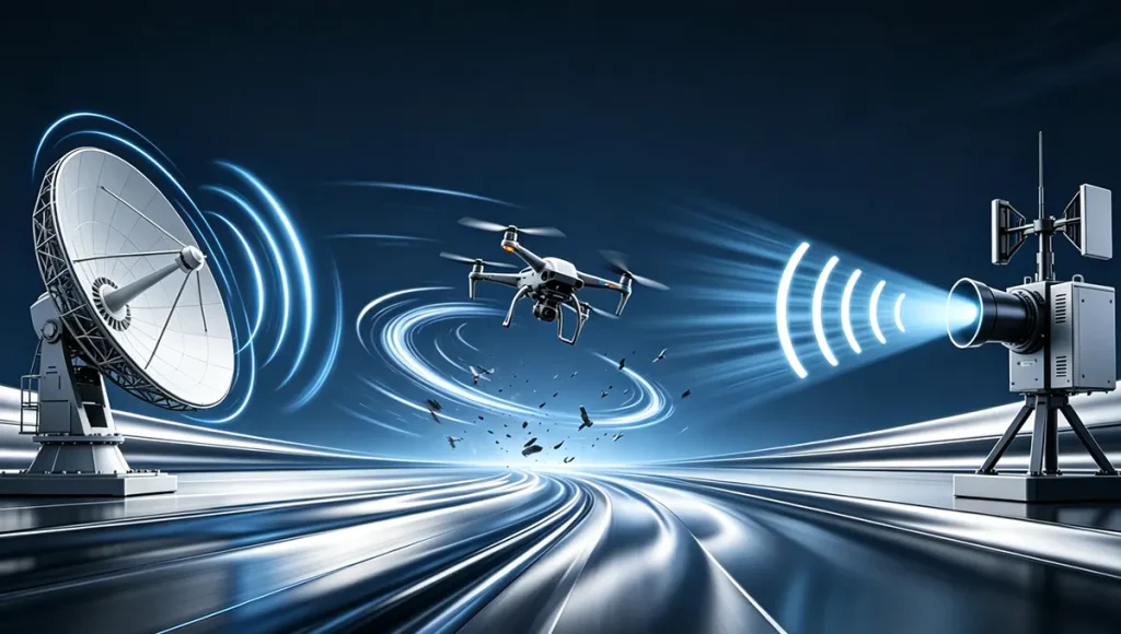
In integrated Counter-Unmanned Aircraft Systems (C-UAS), high-power RF jammers and sensitive detection radars are often deployed on the same physical platform — a single vehicle or tower. When the jammer operates, its tens to hundreds of watts of RF energy couple directly into adjacent receive antennas. The result? Radar detection range collapses. The noise floor rises. The receive channel can even completely saturate.
This is cosite interference.
This paper walks through the RF physics behind cosite interference, presents a three-layer isolation architecture (hardware filtering → antenna placement → TDMA), and provides quantifiable engineering metrics for system integrators who need radar and jammer to actually work together on the same platform.
1. The Problem: What Cosite Interference Really Is
On a typical integrated C-UAS platform, the distance between a jammer antenna and a radar antenna is often just a few meters — sometimes centimeters.
Jammer transmit power: 40 dBm (10W) to 50 dBm (100W)
Radar receiver sensitivity: -90 dBm to -110 dBm
That’s a 140–160 dB gap.
Even a tiny fraction of jammer energy coupling into the receiver is enough to cause serious damage.
Two physical mechanisms are at play.
1.1 Blocking — Front-End Saturation
When jammer energy (or its harmonics) enters the radar’s low-noise amplifier (LNA) and exceeds the LNA’s input 1 dB compression point (IP1dB) , the LNA saturates.
What happens next: LNA gain drops dramatically. The radar can no longer amplify weak drone returns. Detection capability is gone. Recovery time depends on jammer pulse width and LNA characteristics.
A typical LNA has an IP1dB around -20 dBm to -10 dBm. In a cosite scenario, coupled power into the receiver port can reach 0 dBm or higher — well past the safety limit.
1.2 Noise Leakage — The Sneaky One
This is more subtle.
The jammer’s power amplifier (PA) operating in its nonlinear region generates a broadband noise floor that extends far beyond the carrier frequency.
Even if the jammer’s center frequency (say, 2.4 GHz) is far from the radar’s band (X-band or Ku-band), that out-of-band noise still spreads into the radar’s receive band — directly raising the receiver’s noise floor.
The consequence: According to the radar equation, sensitivity is directly tied to system noise temperature. Every 3 dB of noise floor increase cuts detection range by roughly 16%. Field data shows that without effective isolation, cosite deployment can reduce detection range by 50–70%.
2. The Target: How Much Isolation Do You Actually Need?
To keep radar and jammer working simultaneously, the coupled jammer power at the receiver input must stay below the LNA’s IP1dB and must not significantly raise the noise floor.
Assume:
- Jammer transmit power: Pt=50 dBm
- LNA IP1dB: P1dB=−15 dBm
Minimum required isolation:Isolationmin=Pt−P1dB=50−(−15)=65 dB
Add engineering margin (typically 10–15 dB) plus out-of-band noise suppression requirements, and the real-world target lands at 80–100 dB of total isolation.
3. Three-Layer Isolation Architecture: Hardware → Antenna → Timing
No single technique can deliver 80+ dB of isolation. Proven designs use three layers in sequence.
3.1 Layer 1: High-Rejection Cavity Filtering
A high-Q filter must be placed immediately after the jammer’s PA — right at the source — to cut out-of-band noise and spurious emissions.
Selection criteria:
- Metal cavity or high-Q dielectric filter
- Passband insertion loss: <0.5 dB
- Out-of-band rejection (at radar band): ≥60 dBc
- Temperature stability: center frequency drift <±5 MHz over full operating range
Where it sits in the chain:
text
Baseband → Upconverter → Driver Amp → PA → Cavity Filter → Directional Antenna
                                           ↑
                                    Cuts out-of-band noise
Engineering note: Place the filter as close to the PA output as possible to suppress radiation on the transmission path after the PA.
3.2 Layer 2: Antenna Placement and Directional Isolation
After hardware filtering gives you ~60 dB of rejection, the remaining 20–40 dB of isolation comes from antenna placement and directivity.
Vertical separation:
On a mast or tower, separate jammer and radar antennas vertically. Measured data at microwave frequencies:
- Every 0.5 m of vertical separation adds roughly 5–8 dB of isolation
- At 2 m vertical separation, you can get 20–30 dB of isolation
- Horizontal separation is far less effective. Always prefer vertical.
Using antenna nulling:
Use a high-directivity antenna for the jammer (panel antenna, log-periodic, etc.). Aim the back lobe null toward the radar antenna.
A good directional antenna has a front-to-back ratio of 25–30 dB. Use that directivity to gain another 20+ dB of isolation — for free.
3.3 Layer 3: TDMA — Time-Division Coexistence
When hardware and antenna placement hit their limits (think extremely compact platforms), you must move to the time domain. This is temporal coexistence — radar and jammer take turns.
How it works:
- High-precision clock sync: Radar, sensors, and jammer share the same microsecond-accurate clock source (GPS/BeiDou disciplined oscillator or OCXO)
- Dynamic time slot allocation: The timeline is divided into microseconds-length slots
| Slot Type | State |
|---|---|
| Detection Window (Slot 1) | Jammer PA off (quiet). Radar transmits and listens. Sensors monitor. |
| Jam Window (Slot 2) | Radar receiver protected (disconnected or front-end limited). Jammer fires at full power. |
Key timing specs:
- Slot width: typically 100–500 μs
- RF switch transition time: ≤5 μs
- Clock sync accuracy: ≤1 μs
With fast alternation (1–5 kHz switching), the system looks like it’s detecting and jamming simultaneously. In reality, they are completely separated in time.
4. Key Selection Metrics for Cosite Integration
These are the specs you must lock down when evaluating a jammer for cosite deployment:
| Parâmetro | Industry Benchmark | Engineering Meaning |
|---|---|---|
| Out-of-band spurious emissions | ≤ -60 dBc/MHz | Measured at the radar band. Lower (more negative) means less noise pollution to co-located receivers. |
| RF switch transition time | ≤ 5 μs | Rise time from PA quiet to full power. Determines detection window dead time in TDMA mode. |
| Antenna front-to-back ratio | ≥ 25 dB | Higher means less energy leaking backward toward your own radar. |
| Cavity filter out-of-band rejection | ≥ 60 dBc @ radar band | If it’s lower than this, hardware filtering alone won’t support cosite deployment. |
| LNA recovery time | ≤ 10 μs | Time for the receiver to regain normal gain after saturation. Affects effective detection windows under pulsed interference. |
5. Design Verification and Test Methods
During system integration, run these tests to validate cosite performance:
Test 1: Isolation measurement
- Jammer at full power
- Spectrum analyzer connected to radar receive port
- Measure coupled power at radar input (fundamental + harmonics)
Test 2: Detection range degradation
- Baseline: radar detection range against standard drone target (RCS = 0.01 m²) with jammer off
- Re-test with jammer on
- Acceptable degradation: ≤ 20%
Test 3: Noise floor rise
- Record radar noise floor with jammer off
- Measure noise floor at radar operating frequency with jammer on
- Acceptable rise: ≤ 3 dB
Test 4: TDMA timing validation
- High-bandwidth oscilloscope monitoring jammer transmit envelope and radar pulse timing
- Confirm jammer is completely quiet during detection windows, and radar receiver is protected during jam windows
6. Putting It All Together
Cosite interference is one of the most underestimated — and most destructive — problems in integrated C-UAS system integration. There’s a natural physical conflict between a high-power jammer and a high-sensitivity receiver.
Solving it requires system-level thinking:
- Hardware filtering is the foundation. 60 dB of out-of-band rejection is the entry ticket.
- Antenna placement multiplies that gain. Vertical separation plus nulling adds another 20–30 dB.
- TDMA is the safety net. When physical isolation hits its limit, you trade time for space.
For system integrators: demand measured test reports for all the specs above before selection. During site acceptance, run isolation and range degradation tests. That’s how you ensure your C-UAS system can truly detect and jam at the same time — without blinding itself.