
Inhaltsverzeichnis
Radar is a detection and ranging technology that uses transmitted electromagnetic signals and their reflected returns to determine the location, distance, velocity, and shape of objects. The word “radar” is an acronym for Radio Detection And Ranging — a term standardized during World War II that precisely captures what the technology does.
At its simplest, a Radarsystem works like this: it transmits radio waves, waits for them to bounce off an object, and listens for the returning echo. By measuring the time it takes for the signal to travel to the target and back, the radar calculates the target’s distance. By analyzing changes in the signal’s frequency, it determines the target’s velocity. And by processing the returned signal’s angle of arrival and other characteristics, it pinpoints the target’s position in space.
Radar operates across frequency bands from high frequency (HF, roughly 3 MHz) through millimeter-wave (above 30 GHz), with different bands offering different trade-offs between resolution, range, and atmospheric penetration. The IEEE radar band designations — L, S, C, X, Ku, K, Ka, and W — define these frequency ranges, with higher frequencies supporting finer spatial resolution at the cost of greater atmospheric attenuation.
How Radar Works: The Basic Principle
The Transmit-Reflect-Receive Cycle
A radar system typically consists of five core components: a transmitter that generates high-frequency radio signals, an antenna that radiates those signals into space and captures returning echoes, a receiver that amplifies and processes the weak reflected signals, a signal processor that extracts useful information from the received echoes, and a display or data output that presents the results to an operator.
The basic operating cycle is straightforward:
- Senden: The transmitter generates a high-intensity burst of radio-frequency energy, which the antenna radiates as a focused beam.
- Reflect: The electromagnetic waves travel outward at the speed of light. When they encounter an object — an aircraft, a weather system, a drone, or any other target — a portion of the energy scatters or reflects back toward the radar.
- Empfangen: The antenna captures the returning echo, and the receiver amplifies and processes the extremely weak signal.
- Calculate: The system uses the properties of the transmitted and received signals to compute range, velocity, and angle.
Measuring Distance: The Range Equation
Range is the most fundamental measurement a radar makes. The radar measures the round-trip travel time — the interval between when a pulse is transmitted and when its echo returns. Since radio waves travel at the speed of light (approximately 300,000 kilometers per second), the distance to the target is simply:
Range = (Speed of Light × Round-Trip Time) / 2
The division by two accounts for the fact that the signal travels to the target and back — the round-trip distance is twice the range to the target.
Measuring Velocity: The Doppler Effect
Radar determines a target’s velocity through the Doppler effect. When a radar pulse strikes a moving target, the frequency of the returned wave is shifted — compressed if the target is moving toward the radar, stretched if it is moving away. This is the same principle that causes the pitch of a passing siren to drop as it moves past you.
By measuring this Doppler frequency shift between the transmitted and received signals, a radar system can determine the target’s radial velocity — its speed directly toward or away from the radar. Modern weather radars and air-surveillance radars are almost all Doppler radars for this reason.
Measuring Angle: Direction Finding
Radar determines a target’s angular position through the direction in which the antenna is pointing when it receives the echo. In a mechanically scanned radar, the antenna rotates, and the system records the azimuth angle at the moment of the return. In a phased-array radar, the beam is steered electronically, and the system knows the beam’s pointing angle at all times.
Core Components of a Radar System
Every radar system, regardless of its application, relies on the same fundamental building blocks:
In a pulsed radar, the transmitter sends out very brief pulses of radio waves rather than a continuous stream. The radar spends the vast majority of its time listening for returns — in a typical weather radar, for example, the transmitter is active for only about 7 seconds per hour; the remaining 59 minutes and 53 seconds are spent listening.
In a continuous-wave (CW) radar, the transmitter operates continuously, and separate transmit and receive antennas are required to prevent the powerful transmitted signal from overwhelming the sensitive receiver. Frequency-modulated continuous-wave (FMCW) radars add a frequency ramp to the transmitted signal, enabling range measurement alongside Doppler velocity.
Types of Radar Systems
Radar systems come in many configurations, each optimized for different missions and environments:
By Architecture
- Monostatic Radar: Uses a single antenna for both transmission and reception, switching between the two functions with a transmit-receive switch that protects the receiver during the high-power transmit interval. This is the most common radar architecture.
- Bistatic Radar: Separates the transmitter and receiver by a significant distance. This geometry complicates signal processing but offers advantages in survivability and the ability to exploit “illuminators of opportunity” — existing transmitters such as broadcast or communication signals.
- Phased-Array-Radar: Replaces a mechanically rotating dish with a stationary aperture of electronically steerable elements. By adjusting the phase of the signal at each element, the beam can be steered almost instantaneously in any direction. This permits simultaneous tracking of many targets and rapid beam repositioning. Active Electronically Scanned Array (AESA) radars are a key example of this technology.
By Waveform
- Pulsed Radar: Transmits short, high-intensity pulses and listens for returns between pulses. Most surveillance and tracking radars use pulsed waveforms.
- Continuous-Wave (CW) Radar: Transmits continuously and requires separate transmit and receive antennas. CW radars excel at velocity measurement but cannot measure range unless frequency modulation is added.
- Frequency-Modulated Continuous-Wave (FMCW) Radar: Combines continuous transmission with frequency modulation to extract both range and velocity information. FMCW radars are common in automotive and short-range sensing applications.
By Frequency Band
Higher frequency bands offer finer spatial resolution but suffer greater atmospheric attenuation. Lower frequency bands penetrate weather and vegetation more effectively but provide coarser resolution.
Surveillance Radar: Watching Over Airspace
Surveillance radar is a category of radar systems designed for the continuous monitoring of airspace, ground areas, or maritime regions to detect and track objects of interest. Unlike tracking radar, which follows individual targets in detail, surveillance radar maintains a broad picture of an area and detects new targets as they appear.
Types of Surveillance Radar
Air Surveillance Radar is designed for early warning, land and maritime surveillance, detecting fixed-wing aircraft, helicopters, and remotely piloted vehicles. These radars are typically long-range systems that provide a comprehensive picture of air activity in a region.
Airport Surveillance Radar (ASR) monitors air traffic within the vicinity of an airport, typically operating at S-band. ASR systems help air traffic controllers manage arrivals, departures, and en-route traffic safely.
Ground Surveillance Radar monitors ground movement for border security, perimeter protection, and critical infrastructure monitoring. These systems can detect personnel, vehicles, and low-flying aircraft.
Airborne and Space-Based Surveillance Radar takes advantage of extremely large fields of view from elevated platforms. These include Airborne Early Warning (AEW) systems and Space-Based Radars (SBR).
Key Performance Metrics
Surveillance radar performance is assessed through several linked metrics:
- Maximale Erfassungsreichweite: Determined by the radar range equation, which balances transmitted power, antenna gain, target radar cross-section (RCS), receiver noise, and required signal-to-noise ratio.
- Entfernungsauflösung: Equal to the speed of light divided by twice the waveform bandwidth; this sets the minimum separation between two distinguishable targets along the radial direction.
- Cross-Range Resolution: Determined by the antenna beamwidth and the target’s range; for a given antenna size, higher frequencies (shorter wavelengths) provide finer cross-range resolution.
- Update Rate: How frequently the radar completes a full scan of its coverage volume; faster update rates improve track continuity but may reduce sensitivity.
Low-Altitude Surveillance Radar: The Challenge of the “Low, Slow, and Small”
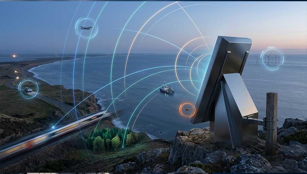
Low-altitude surveillance radar is a specialized category of radar designed to keep watch over low-altitude airspace — the domain below typical air-traffic control radar coverage where drones, low-flying aircraft, cruise missiles, and other threats operate.
What Makes Low-Altitude Surveillance Different?
Low-altitude surveillance presents unique challenges that distinguish it from traditional air-surveillance radar:
First, the targets are often small. A consumer drone has a radar cross-section (RCS) of only 0.01 to 0.02 square meters — comparable to a large bird and far smaller than an aircraft. Detecting such small targets requires high sensitivity and sophisticated signal processing.
Second, the environment is cluttered. Ground clutter — reflections from buildings, terrain, trees, and vehicles — can easily mask the weak returns from low-flying targets. Urban environments are particularly challenging due to the density of reflectors.
Third, the targets are slow and maneuverable. Low-altitude targets can change speed and direction rapidly, making them difficult to track with traditional radar algorithms.
Fourth, the timeline is compressed. Because low-altitude flight occurs close to protected assets, the time between detection and the target reaching its objective is often measured in seconds, not minutes. Traditional automatic target recognition approaches — which rely on track accumulation — can introduce detection response times exceeding 3–5 seconds. Emerging tracking-free ATR methodologies are reducing this to below 100 milliseconds.
How Low-Altitude Surveillance Radar Works
A low-altitude surveillance radar performs several critical functions:
Detection: The radar scans a defined airspace and searches for moving objects of interest. Unlike cameras, radar does not depend on visible light and does not need to know where to look before it starts searching.
Tracking: The radar associates repeated detections over time and turns them into continuous tracks. A track shows range, bearing, height, speed, direction, and recent history. Tracks are more useful than isolated detections because a single point could be noise, a bird, or an environmental reflection.
Alerting: The radar is combined with geofences, warning zones, exclusion zones, and behavioral rules. The system may raise an alert only when a target enters a specific zone, approaches from a sensitive direction, or continues toward a protected asset. Effective alert logic and false-alarm control are often more important than maximum range specifications.
Sensor Cueing: Radar is strong at search and tracking, but it does not visually identify the target. Low-altitude surveillance radar typically cues EO/IR cameras, visible-light video, thermal imaging, or RF detection systems to confirm the target’s identity.
Advanced Low-Altitude Radar Technologies
Modern low-altitude surveillance radars employ several advanced technologies:
Digital Array Technology: Replaces analog beamforming with digital control of each antenna element, enabling more flexible beam patterns and improved clutter rejection.
Software-Defined Radar: Uses programmable signal processing to adapt radar behavior to changing environments and threats.
Cognitive MIMO Radar: Uses multiple-input multiple-output techniques with cognitive processing to observe multiple targets simultaneously and adapt to the environment.
Advanced Clutter Suppression: Employs sophisticated algorithms — including moving target indication (MTI), moving target detection (MTD), and constant false-alarm rate (CFAR) processing — to distinguish targets from background clutter.
Tracking-Free Automatic Target Recognition: A new paradigm that restructures the conventional “Detection–Tracking–Recognition” chain into a parallel “Integrated Detection and Recognition” architecture, achieving detection response times below 100 milliseconds — more than an order of magnitude faster than traditional systems. Field trials using X-band radar have demonstrated reliable identification of VTOL aircraft at ranges exceeding 12 km.
Applications of Radar Technology
Radar technology has expanded far beyond its military origins into a vast array of civilian and commercial applications:
Defense and Security
- Air surveillance and early warning — detecting and tracking aircraft, missiles, and drones
- Border and perimeter security — monitoring ground movement and low-altitude airspace
- Weapon locating and fire control — tracking artillery, mortar, and missile trajectories
- Anti-stealth detection — using low-frequency bands to detect radar-evading aircraft
- Counter-UAV systems — detecting, tracking, and cueing countermeasures against drones
Aviation and Air Traffic Control
- Airport surveillance — managing arrivals, departures, and en-route traffic
- Airborne weather avoidance — detecting hazardous weather for flight safety
- Ground-penetrating and foliage-penetrating radar — for search and rescue, disaster response
Weather and Environmental Monitoring
- Weather surveillance — detecting precipitation, wind shear, and storm structure
- Dual-polarization weather radar — distinguishing rain, hail, snow, and ice pellets
- Tornado and severe weather detection — identifying debris balls and rotation signatures
Remote Sensing and Imaging
- Synthetic Aperture Radar (SAR) — producing high-resolution images from airborne or spaceborne platforms
- Three-dimensional imaging radar — extracting elevation information and creating digital elevation models
- Ground-penetrating radar — subsurface mapping and detection
Commercial and Industrial
- Automotive radar — adaptive cruise control, collision avoidance, autonomous driving
- Maritime navigation — collision avoidance, harbor surveillance
- Industrial sensing — level measurement, presence detection, process control
The Radar Range Equation: A Fundamental Tool
The radar range equation is the fundamental tool that engineers use to predict and understand radar performance:
Pr = Pt × Gt × Gr × σ × λ² / ((4π)³ × R⁴)
Where:
- Pr = received power
- Pt = transmitted power
- Gt = transmit antenna gain
- Gr = receive antenna gain
- σ = target radar cross-section (RCS)
- λ = wavelength
- R = range to the target
The equation reveals a critical insight: received power decreases with the fourth power of range (R⁴). Doubling the range reduces the received signal by a factor of 16. This is why Radarsysteme require enormous transmitted power and sensitive receivers to achieve long detection ranges.
Die radar cross-section (σ) is a measure of a target’s effective scattering area at the radar’s operating frequency. RCS depends on target size, shape, material properties, and the angle of incidence, and it can vary by many orders of magnitude for the same physical object viewed from different aspects. This variability makes detection of small or stealthy targets — such as drones — particularly challenging.
Radar Signal Processing: Extracting Targets from Noise
Raw radar returns contain not only target echoes but also receiver noise, ground clutter, weather returns, and interference. Signal processing is the discipline of extracting useful target information from this noisy data.
Key Signal Processing Techniques
Matched Filtering correlates the received signal against a template of the transmitted waveform to maximize signal-to-noise ratio before any detection decision is made. This is the optimal linear processor for detecting known signals in white noise.
Pulse Compression modulates the transmitted pulse and then compresses the return, allowing a radar to achieve the range resolution of a short pulse while transmitting the energy of a long pulse. This resolves the fundamental trade-off between range resolution and detection range.
Constant False-Alarm Rate (CFAR) Processing adapts the detection threshold dynamically to local clutter statistics, preserving detection performance as background conditions change across a scan.
Moving Target Indication (MTI) und Erkennung beweglicher Ziele (MTD) use Doppler processing to distinguish moving targets from stationary clutter. These techniques are essential for detecting targets in ground-clutter environments.
Doppler Processing extracts velocity information from the frequency shift between transmitted and received signals, enabling the radar to determine target speed and direction.
The Enduring Importance of Radar
Radar has evolved dramatically since its origins in the 1930s, but its fundamental purpose remains unchanged: to extend human perception beyond the limits of sight. Whether watching for weather, guiding aircraft, tracking missiles, or protecting critical infrastructure from drone threats, radar systems provide the situational awareness that modern life and security depend on.
At STARDL, we understand that radar is not a single technology but a diverse family of sensing solutions — each optimized for a specific mission, environment, and set of constraints. From the RF semiconductors that power the front end to the advanced signal processing that extracts targets from noise, every component of a radar system must work in harmony to deliver reliable detection and tracking.