
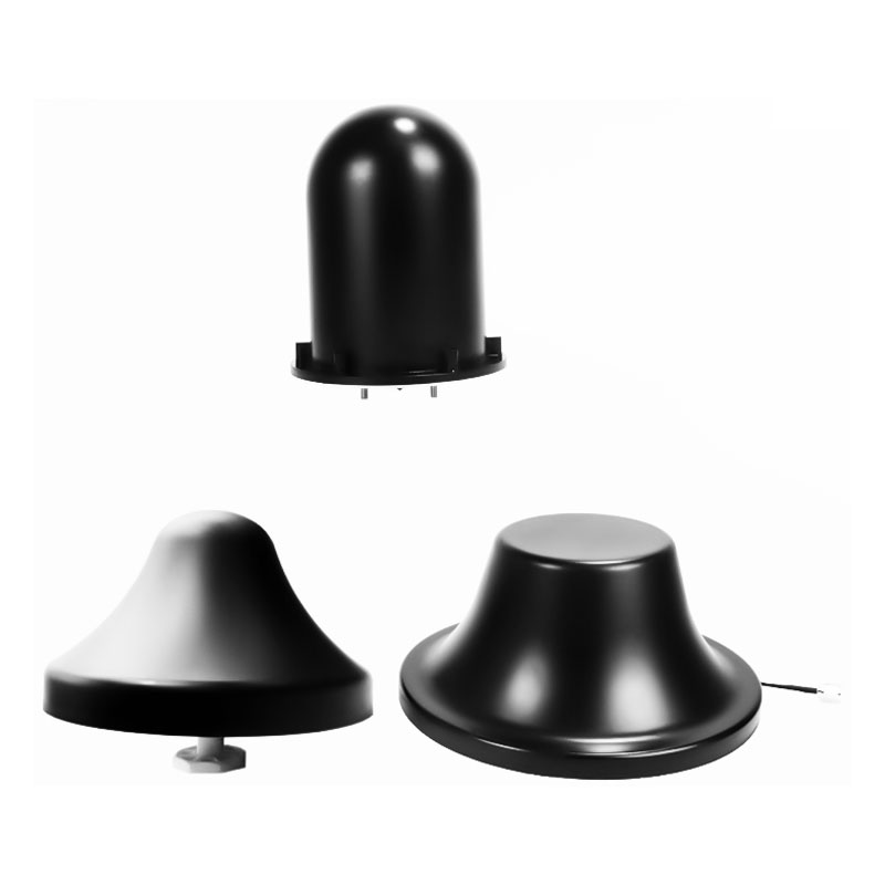
Breitbandige, mehrbandige, omnidirektionale Kuppelantenne
This compact Ø300mm ultra-wideband omni-directional dome antenna delivers uniform 360° horizontal radiation across 300–6200MHz. Rated at 50W, it features up to 6dBi gain for C-UAS and RF deployment.
- True 360° Ultra-Wideband Horizon Coverage
- Optimized Elevation Profile & Multi-Tier Gain
- Excellent Impedance Matching and Power Handling
- Low-Profile Ruggedized Disk Architecture
Produktdetails
Produktmerkmale
An omni-directional antenna features uniform signal radiation across the full 360° horizontal plane, commonly defined as a non-directional antenna. In principle, the narrower the beam width, the higher the antenna gain.
Indikatorparameter
| Häufigkeit | 300-500 / 500-1100 / 1100-1620 / 2400-2500 / 5150-6200MHz |
| VSWR | ≤3.0 / ≤2.0 / ≤1.8 |
| Gain(dBi) | 2 / 3 / 5 / 6±0.5dBi |
| Maximale Eingangsleistung | 50 W |
| Betriebstemperatur | -30 ~ 65℃ |
| Horizontal Beamwidth(°) | 360° |
| Größe | Φ300 × 145mm |
| Anmerkung | Customizable frequency |
Häufig gestellte Fragen
- Q1: Why does the antenna’s gain vary between 2dBi and 6dBi across different frequency bands?
- A1: Antenna gain is fundamentally tied to the electrical size of the internal elements relative to the operating wavelength. At lower frequencies (300-500MHz), the elements behave compactly, yielding a broader vertical beamwidth with a baseline 2dBi gain. At higher bands (5.1-6.2GHz), the vertical beamwidth naturally narrows, tightly focusing the radiated energy along the horizontal plane to achieve higher peak gain values up to 6dBi.
- Q2: What are the engineering advantages of using a single ultra-wideband omni antenna instead of multiple single-band elements?
- A2: Deploying an ultra-wideband (300-6200MHz) integrated architecture drastically reduces physical footprint, wind loading, and structural complexity on mast mounts or vehicle roofs. It eliminates the need for complex external RF combiners or multiplexers, eliminating additional insertion loss and significantly minimizing potential points of failure in multi-frequency RF jamming or monitoring setups.
- Q3: How does the listed VSWR profile (≤3.0 to ≤1.8) impact the safety and transmission efficiency of an attached 50W transmitter?
- A3: The system is engineered to optimize impedance matching where it matters most. While lower VHF/UHF bands tolerate a VSWR of ≤3.0 due to ultra-wideband matching constraints, the critical microwave and drone control bands feature premium matching down to ≤1.8. This ensures that reflected power remains safely within acceptable margins, preventing thermal buildup in the transmitter’s power amplifier while cleanly radiating the full 50W input.
- Q4: Why is a flat 360-degree horizontal beamwidth essential for counter-UAS (C-UAS) and perimeter electronic defense applications?
- A4: In tactical electronic warfare and drone defense, threat vectors can emerge arbitrarily from any azimuth. A non-directional antenna radiating uniformly across a flat 360° horizontal envelope guarantees that no signal blind spots exist, ensuring that defensive electronic countermeasures or monitoring loops maintain instant, equivalent protection regardless of the incoming drone’s flight path.
- Q5: Can the frequency bands of this antenna be customized to target specialized or non-standard communication protocols?
- A5: Yes. The underlying internal matrix supports extensive hardware customization. Our engineering team can modify the internal matching networks and radiation element dimensions to shift, expand, or isolate specific frequency sub-bands anywhere within the 20MHz to 8000MHz spectrum to match proprietary tactical frequencies or regional cellular allocations.
-
Stationäres, integriertes Drohnenerkennungs- und 4-seitiges Störsystem
Drohnen-Störsender-Serie -
Hochleistungsfähiges digitales Multiband-Synthese-Störsystem für Gefängnisse
Serie der Kommunikationsstörgeräte -
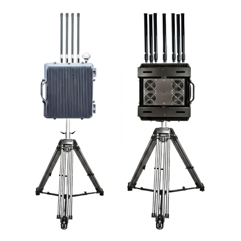
UAV-Detektor und -Abwehrsystem mit integrierten Störsendern, Erfassungsreichweite 1–8 km
Drohnen-Störsender-Serie