

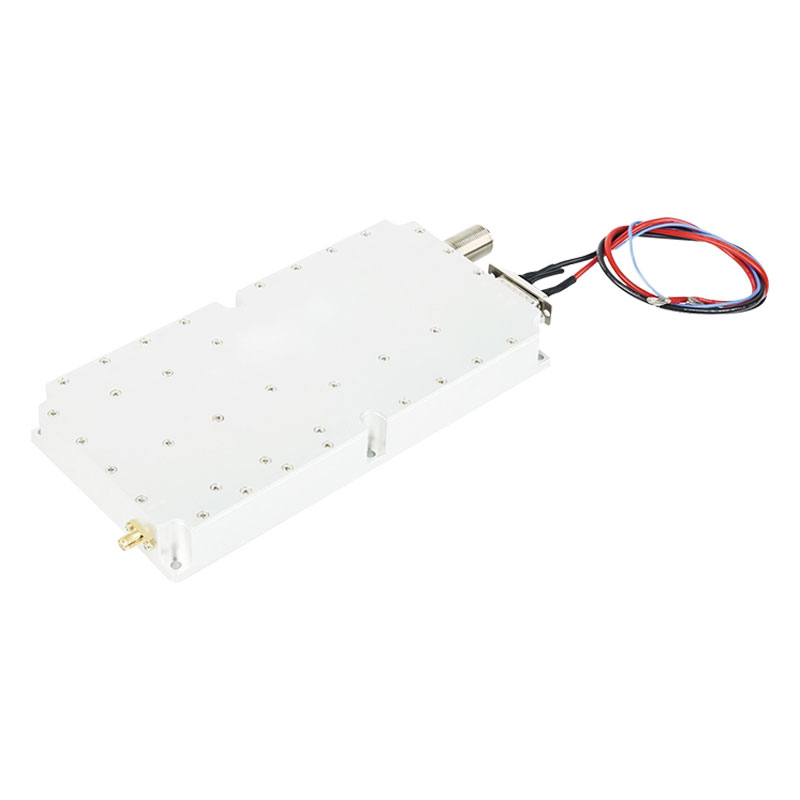
Wideband Class AB GaN Power Amplifier Module
This rugged wideband Class AB GaN power amplifier covers 20MHz to 18GHz. Delivering 5W–200W output with 30%–50% efficiency, it is optimized for radar, electronic jammers, and advanced RF applications.
- High-Efficiency Class AB GaN Architecture
- Exceptional Linear Gain & Flatness
- Built-In Circuit Protection & Telemetry Monitoring
- Rugged, Compact SWaP Interface Layout
Product Details
Product Features
Wideband power amplifiers are commonly used in various frequency band radars, digital jammers, and all types ofRF amplifiers. When paired with digital/analog sources, they can provide stable output.
- Class AB GaN design
- Instantaneous wide bandwidth
- 50 Ohm Input/Output impedance
- Small size and Light weight
- High reliability and Ruggedness
Key Specifications
| Product name | Wide band power amplifier |
| Frequency band | 20MHz-1GHz, 1GHz-3GHz, 3GHz-6GHz, 6GHz-8GHz, 8GHz-10GHz, 10GHz-12GHz, 6Hz-18GHz, 7GHz-12GHz |
| Output power | 5W-200W |
| Power supply | DC 12-32V |
| Running temperature | -20 ~ 85℃ |
| Temp Monitor Voltage | Output Voltage 0.75V@25℃ (1℃/0.01V) |
| Input Power | -2±3dBm (customize) |
| Maximum Input Power at Without Damage | 5dBm |
| Power Gain at Input Power 0dBm | (43-53)±3dB |
| Gain Flatness at Input Power 0dBm | ±3dB |
| Efficiency | 30%-50% |
| Harmonics 1 to N at Output Power 100W | 10dBc |
| Spurious Level | 60dBc |
| Input VSWR | 2.0 |
| Output VSWR | 2.0 |
| RF Connector | MCX Female: RF Input N Female: RF Output |
| DC Connector | Through core capacitor, Male: Supply (Feedthrough capacitor) or cable |
| Cooling | External Heat-sink Required |
FAQ
- Q1: What are the primary advantages of utilizing GaN Class AB technology over traditional LDMOS or GaAs structures in this amplifier?
- A1: GaN (Gallium Nitride) provides significantly higher breakdown voltages, superior power density, and excellent thermal conductivity. Operating in a Class AB topology balances linear performance with high raw power conversion efficiency (30% to 50%), allowing this ultra-compact module to maintain instantaneous wide bandwidths up to 18GHz without sacrificing long-term hardware reliability.
- Q2: How does the integrated temperature monitoring voltage function help prevent thermal runaway during field operation?
- A2: The module incorporates an internal temperature telemetry sensor that outputs a real-time analog DC voltage via the feedthrough capacitor layout. It is precisely calibrated to scale at 0.01V/1°C, reading 0.75V at a baseline room temperature of 25°C. System integrators can monitor this telemetry line to automatically modulate cooling fans or trigger safety overrides before reaching the 85°C maximum operating limit.
- Q3: What operational precautions should be taken regarding the input signal level to avoid damaging the internal RF circuitry?
- A3: This wideband power amplifier is optimized for a nominal customizable input signal drive between -2 and +3 dBm to achieve its rated 43–53dB power gain output. While the internal architecture features high ruggedness and can withstand an absolute maximum input power spike of up to +5 dBm without sustaining permanent damage, keeping signals within nominal limits prevents overdrive compression.
- Q4: Why does this broadband module require an external heat sink, and what are the integration requirements?
- A4: Generating up to 200W of raw RF output power within a compact, lightweight footprint across a versatile DC 12–32V input line creates dense thermal dissipation demands. To maintain consistent gain flatness and ensure internal junction components do not experience thermal stress, the module must be mounted flush against a heavy-duty external heat sink or liquid-cooled plate using high-performance thermal interface materials (TIM).
- Q5: Can this wideband amplifier support multiple distinct sub-bands, and what type of connectors are used for RF and DC lines?
- A5: Yes, the underlying circuit matrix supports several standard sub-band options (such as 20MHz-1GHz, 6-18GHz, and 7-12GHz) to align with specific radar, communication, or digital jammer architectures. For reliable connectivity under vibration, the module utilizes a high-frequency MCX Female interface for RF input, a robust N Female connector for power-stable RF output, and a rugged through-core (feedthrough) capacitor configuration for filtered DC supply input.
-
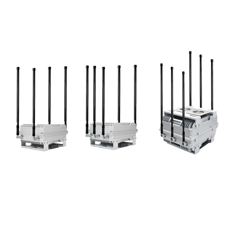
Multi-Band Vehicle-Mounted and Fixed FPV Drone Jammer System
Drone Jammer Series -
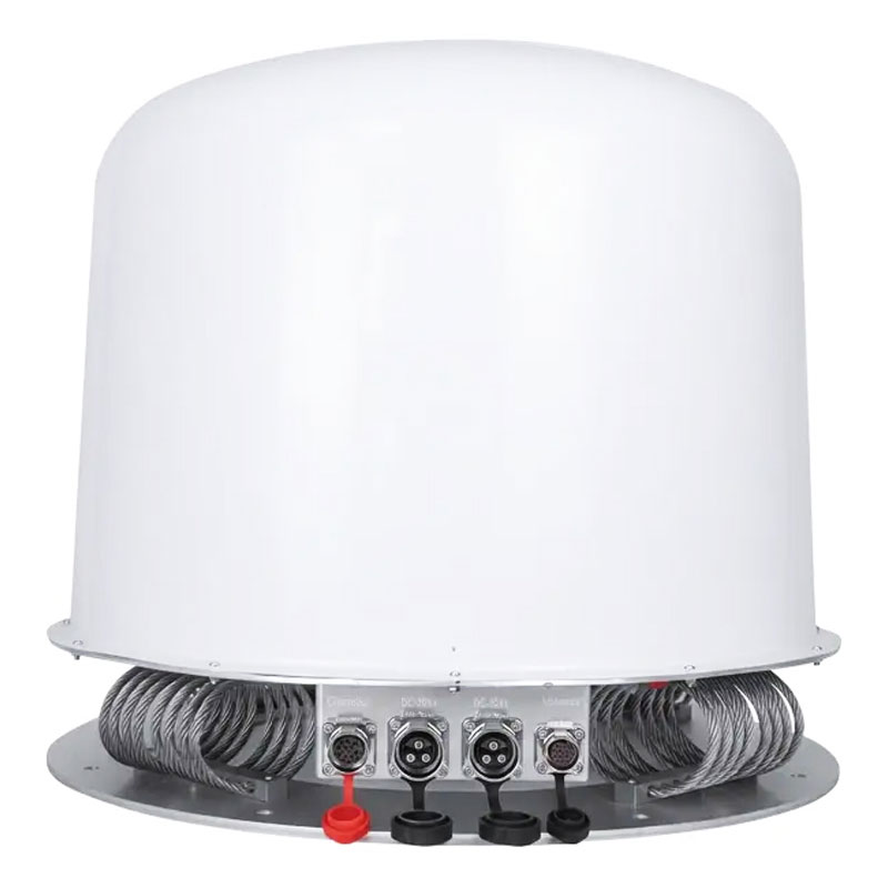
Vehicle-Mounted Integrated Radome 360° High-Power UAV Jammer System
Drone Jammer Series -
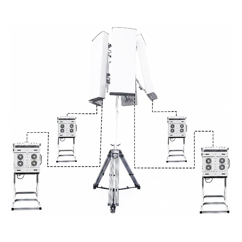
Stationary 360° Directional High-Power Multi-Band UAV Drone Jammer System
Drone Jammer Series -
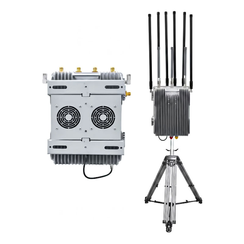
UAV Detector And Counter Integrated Jammers Detection range 1-5Km
Drone Jammer Series