
Índice
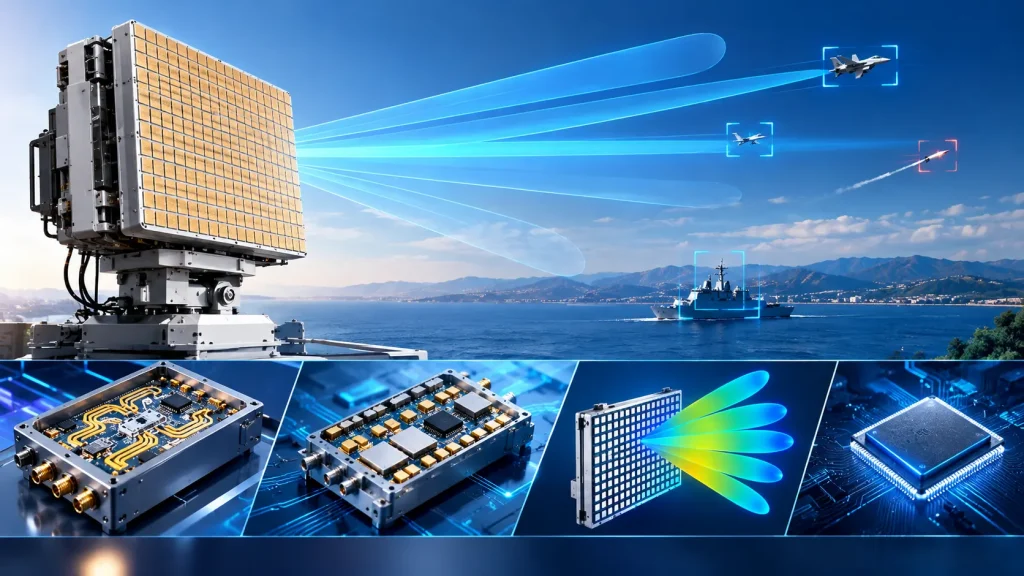
Phased array radar is a radar architecture that electronically controls the phase and amplitude of each element in an antenna array to steer the beam rapidly in space. Unlike mechanical scan radar, which physically rotates the antenna to change beam direction, phased array radar has no moving mechanical parts. The beam can be switched in microseconds, fundamentally changing the radar’s scanning method and multi-target handling capability.
Academician Mao Erke’s research career is closely intertwined with the development of China’s phased array radar. In 1964, at the age of 30, he participated in the design of China’s first phased array radar, making China one of the few countries in the world capable of developing large advanced radars. Looking back, the evolution of phased array radar technology is essentially a paradigm revolution from “mechanical rotation” to “electronic beamforming.”
1. Basic Working Principle of Phased Array Radar
1.1 Beamforming: The Physical Essence of Phase Control
The core mechanism of phased array radar is wave interference. When multiple elements in an antenna array radiate electromagnetic waves simultaneously, the waves from each element superimpose in space. If all elements have the same phase, the beam points in the normal direction of the array. If the phase of each element increases or decreases according to a certain pattern, the superimposed beam deflects.
For a uniform linear array, when the phase difference between adjacent elements is Δφ, the beam deflection angle θ satisfies:
Δφ = 2π · d · senθ / λ
where d is the element spacing and λ is the operating wavelength. By precisely controlling the phase shifter of each element, the beam can be flexibly pointed in any direction within the scan range.
1.2 From Passive to Active: Architectural Evolution
Phased array radar has evolved from passive to active, and from analog to digital.
Passive Electronically Scanned Array (PESA) uses a centralized high-power transmitter, distributing the signal to each antenna element through a feed network. Each element is equipped only with a phase shifter. This architecture is relatively low-cost, but feed losses are high, and reliability is limited by the central transmitter.
Active Electronically Scanned Array (AESA) equips each antenna element with an independent transmit/receive (T/R) module containing a power amplifier, low-noise amplifier, phase shifter, and attenuator. AESA eliminates the centralized transmitter, greatly reducing feed losses and significantly improving system reliability—even if some T/R modules fail, the radar can still operate in a degraded mode.
Digital phased array further moves beamforming from the analog domain to the digital domain. The received signal from each element or subarray is digitized by an ADC and then beamformed by a digital signal processor. Digital beamforming enables flexible reconfigurable beam shapes, simultaneous multi-beam formation, and stronger anti-jamming capability.
2. T/R Modules: The Core Unit of Phased Array Radar
2.1 Functional Composition of a T/R Module
The T/R module is the core functional unit of the AESA radar Circuito de entrada de RF, integrating transmit signal power amplification, receive signal low-noise amplification, phase shifting, and attenuation. In transmit mode, a typical T/R module amplifies the excitation signal to the required power and applies a phase shift. In receive mode, it low-noise amplifies the weak echo signal and applies receive phase weighting.
2.2 Engineering Challenges of High-Density Integration
A large phased array radar may contain thousands or even tens of thousands of T/R modules. These modules must achieve consistent phase and amplitude responses within a limited space; otherwise, beamforming performance degrades severely. Channel-to-channel consistency is one of the most critical engineering challenges in phased array radar.
A study published in 2025 demonstrated a compact T/R module design for an S-band all-digital phased array radar. The transmit side used GaN technology to achieve 10W output power, while the receive chain achieved 33 dB gain and a 3 dB noise figure. The module size was only 46 mm × 38 mm. This compact design allows multiple modules to be integrated together to realize a fully digital radar system.
2.3 The Role of GaN Power Devices in T/R Modules
GaN power amplifier chips offer multiple advantages including small size, wide bandgap, high voltage tolerance, high temperature tolerance, and high power density, making them suitable for high-power phased array radar applications. Within the same T/R module volume, GaN devices can deliver an order of magnitude higher output power than traditional GaAs devices, enabling phased array radar to achieve long-range detection while maintaining a compact structure.
3. Technical Advantages of Phased Array Radar
Extremely fast beam switching. The absence of moving mechanical parts means beam pointing can be switched only by the response speed of the phase shifters, which can be completed in microseconds. This enables phased array radar to implement Track-While-Scan (TWS) mode, performing search and tracking tasks simultaneously.
Multi-target capability. Through digital beamforming, phased array radar can simultaneously form multiple beams pointing in different directions, enabling simultaneous tracking of multiple targets. A 2025 study demonstrated a phased array radar system based on a 30×30 uniform rectangular array, using a hybrid robust beamformer and achieving 99.29% overall accuracy in multi-target detection and interference suppression.
Strong anti-jamming capability. Phased array radar can form nulls in the direction of interference sources through adaptive beamforming, effectively suppressing intentional or unintentional interference. Digital beamforming gives the radar multi-dimensional anti-jamming capabilities in the spatial, temporal, and frequency domains.
High reliability. The distributed T/R module architecture of AESA radar means that failure of a single module does not paralyze the entire system. The radar can compensate for performance loss by reassigning tasks, offering extremely high tactical value in military applications.
4. Key Technical Challenges of Phased Array Radar
4.1 Grating Lobe Suppression
When element spacing exceeds half a wavelength, additional beams appear at other angles besides the main lobe—these are grating lobes. Grating lobes cause transmit energy dispersion and receive angle ambiguity. In engineering, element spacing is typically kept strictly within λ/2, but this means the number of elements increases sharply with frequency, driving up cost, power consumption, and volume.
4.2 The Contradiction Between Wideband and Wide-Angle Scanning
The beamwidth of a phased array radar varies with scan angle—narrowest when pointing at the normal, and widening at large angles, causing gain reduction and resolution degradation. This is a physical law of array antennas and cannot be eliminated; system design can only limit the scan range to an acceptable range (typically within ±60°).
4.3 Thermal Management
High-density integrated T/R modules generate substantial heat within a limited space. Although GaN power amplifiers are efficient, their heat flux density is also more concentrated. Effective thermal management solutions—including high-thermal-conductivity substrates, liquid cooling systems, and rational module layout—are key to the engineering implementation of phased array radar.
5. Development Directions of Phased Array Radar
According to a technical review published in 2026, phased array antenna technology is developing toward six dimensions: lightweight, integrated, low-scattering, multi-functional, distributed, and intelligent.
Lightweight is an urgent requirement for airborne and satellite platforms. Chip-level phased arrays and 3D micro-nano integration are key technical paths to achieving lightweight designs. Integration requires breaking through the limitations of traditional single apertures to achieve integrated deployment of comprehensive platform apertures. Intelligence targets future adaptive radar requirements, requiring phased arrays to possess front-end capabilities for integrated processing and intelligent scheduling.
These development directions impose higher demands on the RF front-end—wider bandwidth, higher integration, lower power consumption, and stronger environmental adaptability.
6. STARDL’s Technology Portfolio for Phased Array Radar RF Front-Ends
The performance bottleneck of phased array radar is concentrated in the RF front-end—transmit power and efficiency determine detection range, receiver noise figure determines the sensitivity ceiling, and signal chain phase consistency determines beamforming quality. STARDL’s RF front-end technology portfolio provides complete hardware support for phased array radar:
Cadena de transmisión: dispositivos de potencia de GaN. STARDL’s GaN power devices cover the 0.5–8.0 GHz band with output power up to 100W+, featuring pre-matched internal impedance networks that maintain stable linearity under pulsed operation. GaN’s high power density and excellent thermal stability make it an ideal transmit device for high-power phased array radar T/R modules.
Cadena de recepción: amplificadores de bajo ruido. The noise figure of the phased array radar receive chain directly determines the system’s sensitivity ceiling. STARDL’s LNAs are based on GaAs process, achieving noise figures as low as 0.35 dB while maintaining good linearity, meeting the strict consistency and stability requirements of multi-channel phased array radar reception.
Cadena de señal: circuitos integrados de radiofrecuencia y microondas. The beamforming accuracy of phased array radar depends on the phase consistency of each channel. STARDL’s RF microwave ICs cover DC to 50 GHz, from mixers to multipliers to phase shifters, forming a complete signal-chain solution. Low phase noise design directly affects beamforming quality and Doppler processing accuracy.
System Integration – T/R Modules and Packaged ICs. STARDL’s expertise in T/R modules addresses the core problem of “achieving stable multi-channel operation within limited space.” Packaged ICs cover DC to 40 GHz and are compatible with standard SMT processes, providing high-density, high-consistency integration solutions for the engineering and volume production of phased array radar.
7. Selection Comparison: Phased Array Radar vs. Mechanical Scan Radar
| Dimensión | Phased Array Radar | Mechanical Scan Radar |
|---|---|---|
| Beam Switching Speed | Microseconds (electronic control) | Seconds (mechanical rotation) |
| Capacidad multiobjetivo | Strong (simultaneous multi-beam tracking) | Weak (sequential single-beam tracking) |
| Capacidad anti-interferencias | Strong (adaptive nulling) | Weak (no spatial filtering capability) |
| Reliability | High (distributed T/R modules) | Medium (mechanical parts wear) |
| Cost | High (large number of T/R modules) | Low (simple structure) |
| Aplicaciones típicas | High-end military radar, satellite communication terminals | Weather radar, marine navigation radar |
La realidad de la ingeniería
The essence of phased array radar is replacing mechanical means con electronic means to control the beam, liberating radar from the physical constraint of “rotating an antenna” and gaining the freedom of beamforming and the flexibility of multi-target processing.
Academician Mao Erke participated in the design of China’s first phased array radar at the age of 30 and continued to promote research on new-architecture radars for decades thereafter. The directions he proposed—synthetic wideband high-resolution radar, full-space-time radar, distributed coherent radar—all share a core idea: obtain more target information by improving resolution—and phased array technology is one of the most powerful means of achieving this goal.
STARDL’s technology portfolio in RF front-ends—from GaN power devices to low-noise amplifiers, from RF microwave ICs to T/R modules—covers the complete hardware chain from transmit to receive for phased array radar, providing a solid RF foundation for the engineering implementation of next-generation phased array radar systems.