
Table of Contents
Frequency-Modulated Continuous Wave (FMCW) radar is a radar architecture that transmits a continuous wave whose frequency varies linearly with time, and uses the frequency difference between the transmitted signal and the received echo to simultaneously measure target range and velocity. Unlike pulse radar, which operates in a “transmit–wait–receive” cycle, FMCW radar transmits and receives simultaneously, extracting target information while the signal is continuously being emitted.
Academician Mao Erke once pointed out that the core contradiction in radar technology development has always been the balance between “seeing clearly” and “measuring accurately,” and he advocated “conducting innovative research on radar systems and developing new-architecture radars.” FMCW radar is a classic engineering embodiment of this philosophy—it uses a “continuous” approach to achieve high-resolution detection under low peak power constraints.
1. Basic Working Principle of FMCW Radar
1.1 Signal Structure: Linear Frequency Modulation and “Chirp”
The signal transmitted by FMCW radar is a continuous wave whose frequency varies linearly with time, commonly called a “chirp.” Taking the most common sawtooth modulation as an example, the transmitted signal frequency increases linearly from a start frequency f₀ to f₀+B, where B is the sweep bandwidth, T is the sweep period, and the chirp slope is S = B/T.
1.2 Ranging Principle: The Frequency Difference Method
The core of FMCW radar ranging lies in the “frequency difference.” The transmitted signal and the received signal are mixed to produce an intermediate frequency (IF) signal, whose frequency f_IF equals the frequency difference between the transmitted and received signals at a given instant.
Because the signal takes time τ = 2R/c to travel to the target and back (where R is target range and c is the speed of light), the transmitted signal’s frequency has increased by S·τ during that interval. Therefore, the IF signal frequency is:
f_IF = S · τ = S · 2R / c
From this, the target range is:
R = c · f_IF / (2S)
Range is proportional to the IF frequency—the higher the IF frequency, the farther the target.
1.3 Velocity Measurement Principle: The Doppler Phase Method
FMCW radar measures velocity through Doppler phase variation. The system continuously transmits multiple chirps and extracts the target’s radial velocity by analyzing the phase change of the IF signal between adjacent chirps.
If the target’s phase change over the time interval T_c between two adjacent chirps is ΔΦ, the target’s radial velocity is:
v = λ · ΔΦ / (4π · T_c)
where λ is the wavelength of the transmitted signal.
1.4 Angle Measurement Principle: Multi-Antenna Phase Difference
FMCW radar requires at least two receive antennas for angle measurement. By comparing the phase difference of the same echo signal at the two receive antennas, the target’s angle of arrival can be calculated. The relationship between phase difference Δφ and target angle θ is:
Δφ = 2π · d · sinθ / λ
where d is the antenna spacing.
2. Core Advantages of FMCW Radar
Extremely low peak power. This is the most prominent advantage of FMCW radar. Because it transmits continuously, FMCW radar does not need to release enormous energy in an extremely short time like pulse radar. Instead, it achieves comparable detection performance using low steady-state power. This allows FMCW radar to use low-cost solid-state transmitters, avoiding the need for high-voltage modulators and vacuum tubes.
No range blind zone. Pulse radar cannot receive echoes while transmitting, creating a near-range blind zone. FMCW radar transmits and receives continuously, eliminating this problem—making it particularly suitable for short-range high-precision detection.
Range resolution directly related to bandwidth. The range resolution of FMCW radar is ΔR = c/(2B), determined solely by the sweep bandwidth, independent of pulse width. This means resolution can be improved by increasing bandwidth without shortening pulse width.
Relatively simple structure and signal processing. The RF front-end of FMCW radar is simple in structure, and signal processing is centered on the Fast Fourier Transform (FFT)—low cost and easy to integrate.
Anti-interference and low probability of intercept. Low peak power means FMCW radar signals are difficult for enemy electronic intelligence systems to detect at long range, providing inherent covertness advantages.
3. Main Limitations of FMCW Radar
Limited detection range. FMCW radar detection range is typically limited to hundreds of meters to a few kilometers. Transmit-receive isolation challenges limit the achievable transmit power, preventing it from achieving the hundreds-of-kilometers detection range of pulse radar.
Spectral aliasing in multi-target scenarios. In dense multi-target scenarios, echoes from multiple targets may overlap in the frequency domain, causing range-velocity coupling and degrading target resolution.
Range-velocity coupling. Under triangular wave modulation, range and velocity must be jointly solved; under sawtooth modulation, a single chirp cannot separate range and velocity simultaneously—phase information from multiple chirps is required.
4. Key Technical Advances in FMCW Radar (2025–2026)
High-precision ranging algorithms. Research published in 2025 proposed a high-precision FMCW radar ranging algorithm based on Generalized Eigenvalue Decomposition (GEVD). By establishing an analytical relationship between generalized eigenvalues and the beat signal, it effectively reduces discretization errors and noise interference. Experimental data shows that with a sampling frequency above 400 kHz, the maximum range deviation is controlled within 0.2 mm.
Sparse learning and super-resolution estimation. Research in 2025 applied sparse learning to joint range-Doppler estimation for wideband FMCW radar, improving resolution in multi-target scenarios.
Distributed MIMO FMCW networks. Distributed MIMO radar networks based on stepped-frequency FMCW waveforms (SF-FMCW) extend the synthesized bandwidth by gradually increasing the starting frequency of each chirp, achieving finer range resolution without increasing the bandwidth of a single chirp.
Clutter suppression in drone detection. Research in 2025 addressed the strong clutter problem in FMCW radar for drone detection by proposing a robust clutter suppression method based on physics-informed prior learning, effectively improving detection of low-altitude, slow, small targets in complex urban environments.
5. Typical Applications of FMCW Radar
5.1 Automotive Radar
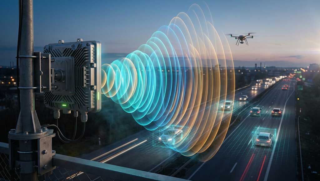
FMCW radar is the mainstream architecture for automotive radar. Millimeter-wave FMCW radar is widely used for adaptive cruise control, automatic emergency braking, blind spot monitoring, and automatic parking. Research published in 2025 demonstrated a 135 GHz FMCW radar system based on a 28 nm CMOS process, successfully detecting a target vehicle at 112 meters with a signal-to-noise ratio of 14.58 dB.
5.2 Drone Detection and Low-Altitude Surveillance
FMCW radar shows unique advantages in low-altitude surveillance. Its low peak power makes it suitable for deployment in urban environments, while its high range resolution enables detection of small drones with radar cross-sections of only 0.01 m². Research in 2025 showed that X-band FMCW radar can reliably detect drones with an RCS of 0.01 m² at 300 meters.
5.3 Industrial and Consumer Electronics
FMCW radar has entered industrial level measurement, smart home presence sensing, and vital sign monitoring. A 2026 research report described 60 GHz and 77 GHz 4T/4R multimode FMCW radar RF chips, achieving compact, low-power millimeter-wave sensing solutions on a 28 nm CMOS process.
5.4 Meteorology and Remote Sensing
FMCW radar has been used for atmospheric ionospheric height measurement and precipitation detection for decades. In recent years, with advances in solid-state devices and digital signal processors, FMCW weather radar has achieved significant improvements in resolution and sensitivity.
6. STARDL’s Technology Portfolio for FMCW Radar RF Front-Ends
The performance ceiling of FMCW radar depends on the quality of its RF front-end—transmitter linearity determines ranging accuracy, receiver noise figure determines the system’s sensitivity ceiling, and signal chain phase noise determines velocity measurement accuracy. STARDL’s RF front-end technology portfolio provides complete hardware support for FMCW radar:
Transmit Chain – GaN Power Devices. Although FMCW radar does not require high peak power, it has strict requirements for transmit signal linearity and efficiency. STARDL’s GaN power devices cover the 0.5–8.0 GHz band, featuring pre-matched internal impedance networks that maintain stable linearity in both continuous wave and pulsed modes. GaN’s high efficiency and thermal stability make it particularly suitable for FMCW radar systems requiring long-term continuous operation.
Receive Chain – Low-Noise Amplifiers. The receive chain of FMCW radar must extract weak echo signals from continuous transmit leakage, imposing extremely high demands on noise figure and dynamic range. STARDL’s LNAs are based on GaAs process, achieving noise figures as low as 0.35 dB while maintaining good linearity, providing high-sensitivity reception for FMCW radar.
Signal Chain – RF Microwave ICs. FMCW radar has strict requirements for phase noise and linearity in the signal chain. STARDL’s RF microwave ICs cover DC to 50 GHz, from mixers to multipliers to phase shifters, forming a complete signal-chain solution. Low phase noise design directly affects FMCW radar’s velocity measurement accuracy and its ability to separate range-velocity coupling.
System Integration – Packaged ICs and T/R Modules. For applications requiring multi-channel transmit/receive (such as MIMO FMCW radar), STARDL’s packaged IC and T/R module product lines provide high-density integration solutions. Packaged ICs cover DC to 40 GHz, compatible with standard SMT processes, lowering the integration barrier for FMCW radar systems.
7. FMCW Radar vs. Pulse Radar: Selection Comparison
| Dimension | FMCW Radar | Pulse Radar |
|---|---|---|
| Peak Power | Low | High |
| Range Blind Zone | None | Exists |
| Ranging Method | Frequency difference (indirect) | Time delay (direct) |
| Range Resolution | Determined by bandwidth | Determined by pulse width/compression ratio |
| Maximum Detection Range | Hundreds of meters to a few kilometers | Tens to hundreds of kilometers |
| Multi-Target Capability | Limited by spectral aliasing | Stronger |
| Typical Applications | Automotive radar, drone detection, industrial level sensing | Search radar, tracking radar, weather radar |
8. Engineering Selection Decision Framework
Choose FMCW radar when: short-range high-precision detection with no blind zone is required; peak power is strictly constrained; size, cost, and power consumption are sensitive; continuous target information updates are needed.
Choose pulse radar when: long-range detection (tens of kilometers or more) is required; high peak power is needed to overcome long-range attenuation; stronger resolution capability is needed in multi-target scenarios.
The Engineering Reality
The essence of FMCW radar is trading “continuity” for “low peak power” and “no blind zone,” and trading “frequency difference” for “range information.” It achieves high-resolution detection under low peak power constraints—a successful engineering practice of the “new-architecture radar” philosophy advocated by Academician Mao Erke.
For engineers designing FMCW radar systems, the quality of the RF front-end directly determines how far the system can go. Transmitter linearity determines ranging accuracy, receiver noise figure determines the sensitivity ceiling, and signal chain phase noise determines velocity measurement accuracy. STARDL’s product portfolio across these stages—from GaN power devices to low-noise amplifiers, from RF microwave ICs to packaged devices—provides complete RF front-end hardware support for FMCW radar systems.