
Table of Contents
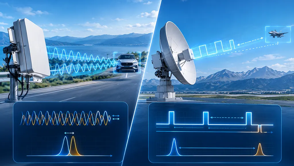
Continuous wave (CW) radar transmits electromagnetic waves continuously while simultaneously receiving echoes, measuring target velocity through the Doppler shift but unable to measure range directly. Pulse radar periodically transmits short, high-power pulses and listens for echoes between pulses, calculating target range directly by measuring the time delay between transmission and reception. The fundamental difference lies in the time structure of the signal—CW radar “keeps talking and keeps listening,” while pulse radar “speaks once, then listens.”
Academician Mao Erke once pointed out that the core contradiction in radar technology development has always been the balance between “seeing clearly” and “measuring accurately.” The difference between CW radar and pulse radar is, in essence, an engineering solution to this contradiction under different physical constraints.
1. Continuous Wave Radar: The Velocity Specialist with Continuous Illumination
A CW radar’s transmitter operates continuously, with no pulse intervals. This means the transmit and receive signals overlap completely in time, requiring physically separate transmit and receive antennas—otherwise the transmit signal would leak directly into the receive channel and drown out the weak echo.
1.1 Working Principle
CW radar extracts target velocity by measuring the Doppler shift between the transmitted and received signals. When a target moves toward the radar, the echo frequency increases; when it moves away, the echo frequency decreases. By computing the cross-correlation of the two signals and applying low-pass filtering, the Doppler shift can be extracted, and the target’s radial velocity estimated.
The velocity resolution of CW radar is inversely proportional to the observation time T—the longer the observation, the more precise the velocity measurement.
1.2 The Physical Root of Its Inability to Measure Range
Unmodulated CW radar cannot measure range. The reason: the transmit signal is continuous with no time markers, so the receiver cannot determine which instant of the transmitted signal the echo corresponds to. The lack of a phase reference makes the echo’s phase offset ambiguous to the receiver, and range information cannot be extracted from the signal.
This limitation gives traditional CW radar a very specific application niche: scenarios where only velocity information is needed, and range is not. Police speed guns, motion detectors, burglar alarms, and proximity fuzes are typical examples of this principle.
1.3 Frequency-Modulated Continuous Wave (FMCW): Compensating for the Ranging Shortfall
To retain the advantages of CW while gaining ranging capability, FMCW radar adds frequency modulation to the transmitted signal. By transmitting a signal whose frequency varies linearly with time and comparing the frequency difference between transmit and receive signals, both range and velocity can be calculated simultaneously.
The core advantage of FMCW radar is its extremely low peak power. Because it transmits continuously, FMCW radar can achieve comparable detection performance using steady-state power two to three orders of magnitude lower than pulse radar. This makes FMCW radar the mainstream choice for automotive radar, drone obstacle avoidance, and short-range high-precision detection.
2. Pulse Radar: The Engineering Cornerstone of Time-Delay Ranging
Pulse radar periodically transmits short, high-power pulses and “listens” for echoes between pulses. Since transmission and reception are separated in time, a single antenna can be used for both, with a transmit-receive switch protecting the receiver.
2.1 Working Principle
The physical principle of pulse radar ranging is extremely clear: measure the time delay between the transmitted pulse and the received echo, multiply by the speed of light, and divide by two—that is the target range.
The core performance parameters of pulse radar are pulse width and pulse repetition frequency (PRF) . Pulse width determines range resolution—the shorter the pulse, the smaller the minimum distance between two resolvable targets. PRF determines the maximum unambiguous detection range—a higher PRF means more pulses per unit time, but a shorter interval between pulses, so echoes from distant targets may be confused with echoes from the next pulse.
2.2 The Pulse Width Dilemma
Pulse radar design always faces a fundamental contradiction:
Short pulses provide good range resolution and minimum range, but limited energy and poor long-range detection. Long pulses provide more energy and longer detection range, but degraded range resolution and a larger near-range blind zone.
This contradiction is resolved in engineering through pulse compression. A wide pulse is transmitted (ensuring energy), with frequency or phase modulation applied within the pulse. On reception, matched filtering compresses the wide pulse into a narrow pulse (restoring resolution). The compression ratio equals the product of pulse width and bandwidth—a 100-microsecond pulse with 10 MHz bandwidth is equivalent to a 0.01-microsecond pulse resolution.
2.3 Pulse Doppler Radar: Unifying Ranging and Velocity Measurement
Pulse radar can also measure target velocity through the Doppler effect. Pulse Doppler radar adds Doppler processing to the pulse architecture, extracting velocity information by analyzing phase changes between successive echo pulses.
The key challenge for pulse Doppler radar is the trade-off between range ambiguity and velocity ambiguity. Low PRF provides a large unambiguous range but suffers velocity ambiguity; high PRF provides a large unambiguous velocity but suffers range ambiguity. In engineering, staggered PRF or multiple-PRF ambiguity resolution techniques are typically used to satisfy both range and velocity measurement requirements.
3. Core Differences Comparison
| Dimension | Continuous Wave (CW) Radar | Pulse Radar |
|---|---|---|
| Signal Structure | Continuous transmission, no pulse intervals | Periodic short pulses with gaps |
| Ranging Capability | None (unless frequency modulated) | Direct time-delay measurement, high accuracy |
| Velocity Measurement | Excellent, direct Doppler measurement | Requires pulse Doppler processing |
| Peak Power | Low (steady-state power suffices) | High (energy released in short bursts) |
| Transmit/Receive Antennas | Must be physically separated | Can be shared, requires TR switch |
| Range Blind Zone | None (continuous reception) | Exists (cannot receive during pulse) |
| Typical Applications | Speed guns, proximity fuzes, FMCW automotive radar | Search radar, tracking radar, weather radar |
4. Engineering Selection Decision Framework
Academician Mao Erke emphasized in his discussions on radar technology development: “The radar systems we need to research are not traditional, mature radars, nor simple copies of advanced foreign radars. They should be new-architecture radars that conform to the laws of radar technology development and actual needs.” This thinking applies equally to the selection between CW and pulse radar—there is no “better” architecture, only a “more suitable” solution.
Choose pulse radar when:
- Precise range measurement is required (e.g., search radar, tracking radar, weather radar)
- Both range and velocity information are needed (pulse Doppler radar)
- Long detection range is required, demanding high peak power
- Track-while-scan (TWS) capability is needed
Choose CW/FMCW radar when:
- Only velocity information is needed, not range (e.g., police speed guns)
- Peak power is strictly limited (e.g., automotive radar, portable devices)
- Extremely low probability of intercept and electromagnetic interference is desired
- Short-range high-precision detection with sensitivity to size and power consumption
5. STARDL’s RF Front-End Portfolio for Both Radar Architectures
Whether for CW or pulse radar, RF front-end performance is the core determinant of system capability. Pulse radar requires high-peak-power transmit chains and fast-recovery receive protection; CW radar requires ultra-low-noise receive chains to extract weak continuous echoes. STARDL’s radar RF front-end portfolio covers the critical requirements of both architectures:
Transmit Chain – GaN Power Devices – The core of pulse radar lies in high-peak-power transmission. STARDL’s GaN power devices cover the 0.5–8.0 GHz band with output power up to 100W+, featuring pre-matched internal impedance networks that maintain stable linearity under pulsed operation. GaN’s high power density and fast switching characteristics make it the ideal choice for pulse radar transmitters.
Receive Chain – Low-Noise Amplifiers – CW radar must extract weak echo signals from strong continuous transmit leakage, imposing extremely high demands on the receive chain’s dynamic range and noise figure. STARDL’s LNAs are based on GaAs process, achieving noise figures as low as 0.35 dB while maintaining good linearity.
Signal Chain – RF Microwave ICs – Both pulse radar’s pulse compression and CW radar’s Doppler extraction impose stringent requirements on phase noise and linearity of the RF front-end. STARDL’s RF microwave ICs cover DC to 50 GHz, from mixers to multipliers to phase shifters, providing complete signal-chain solutions.
System Integration – T/R Modules – Whether for pulse phased-array T/R modules or multichannel CW receive arrays, high-density integration is an engineering challenge. STARDL’s expertise in T/R modules provides a solid hardware foundation for both radar architectures.
The Engineering Reality
The core difference between CW radar and pulse radar lies in the time structure of the signal—CW radar “keeps talking,” pulse radar “speaks once, then listens.” This difference determines the disparity in ranging capability, peak power requirements, and application scenarios.
CW radar achieves precise velocity measurement with extremely low peak power but cannot measure range directly. Pulse radar trades high peak power for direct ranging capability but faces the dilemma between pulse width and resolution. FMCW radar, as an improved form of CW, compensates for the ranging shortfall through frequency modulation and has become mainstream in short-range high-precision scenarios.
Which architecture to choose depends on the mission requirements: Is range or velocity information needed? Is peak power constrained? What detection range is required? Understanding these physical constraints transforms selection from a simple comparison of “which is more advanced” into a systematic judgment of “which is more suitable for this mission.”
STARDL’s radar RF front-end portfolio—from GaN power devices to low-noise amplifiers, from RF chips to T/R modules—provides complete hardware support for both CW and pulse radar architectures.